

Photogrammetry is the science and technology of obtaining reliable information about physical objects and the environment from photographs, and photogrammetry turns overlapping photographs into measurements, maps, and 3D models by matching shared points across views and calculating positions in three dimensions. The method serves mapping, construction, heritage work, farming, filmmaking, and research. Photogrammetry starts with planned photographs, continues through software matching and triangulation, and ends with a point cloud, a mesh, an orthomosaic, or a digital elevation model. Readers learn the definition, the work steps, the main types, the outputs, the uses, the accuracy limits, and a first project plan in this guide. The guide also compares photogrammetry with LiDAR, explains accuracy checks, and gives a first project plan for phone and drone users.
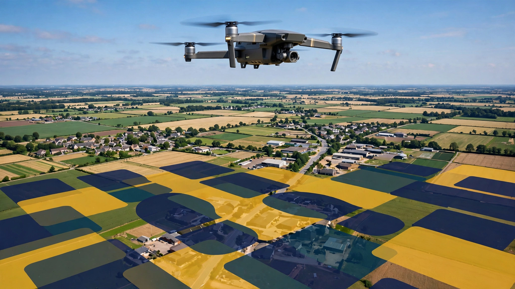
- Photogrammetry measures the real world from overlapping photographs, and photogrammetry software builds maps and 3D models from matched points.
- Overlap, steady light, and sharp photos decide output quality, and ground control points tie results to real-world coordinates.
- Aerial, terrestrial, close-range, and spaceborne photogrammetry differ by camera position, scale, and detail.
- Outputs include point clouds, textured meshes, orthomosaics, and digital elevation models for maps, checks, and records.
- Photogrammetry records colour and texture well, while LiDAR measures through vegetation and in low light with direct laser ranges.
- A phone camera, a planned photo path, and free or low-cost software can support a first small project.
What Is Photogrammetry?
Photogrammetry is the science and technology of obtaining reliable information about physical objects and the environment through recording, measuring, and interpreting photographic images. Photogrammetry software matches shared points in many views, calculates camera positions, and builds measurements, maps, and 3D models from the matched points.
The word photogrammetry joins photo, gram, and metry, and the parts point to light, drawing, and measurement. The term photogrammetry appeared in an 1867 article by German architect Albrecht Meydenbauer, while the method traces to Aimé Laussedat (Source: Wikipedia, 2026). Photogrammetry began with plotted contour lines on topographic maps from stereo plotters, and photogrammetry now covers the wider field described on the photogrammetry history and methods page. Photogrammetry works with phone cameras, handheld cameras, drone cameras, aircraft cameras, and satellite sensors, and the photo plan matters more than the camera. A clear photo set needs overlap, sharp focus, steady exposure, and views of each part of the subject from at least two positions. Readers who want more technology explainers can explore the Tech section for guides on software, devices, and digital methods.
Photogrammetry turns overlapping photographs into measurements, maps, and 3D models without touching the subject.
How Does Photogrammetry Work?
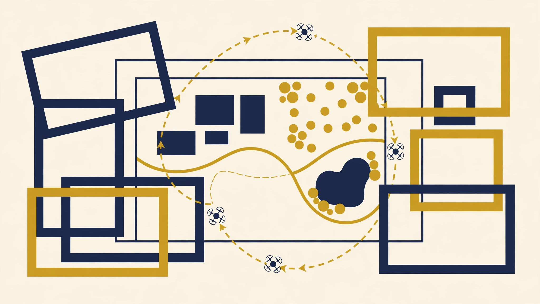
Photogrammetry works by matching the same visible points across overlapping photographs, calculating camera positions from those matches, and triangulating each point into three-dimensional coordinates. Photogrammetry software then builds a dense point cloud, a mesh, and a textured model from the calculated points.
The process follows 6 steps, and each step feeds the next step with checked data.
- Plan the photo path, overlap, light, and control points.
- Capture overlapping photos with fixed exposure and focus settings.
- Import photos, check sharpness, and remove blurred or duplicate photos.
- Align photos, match shared points, and calculate camera positions.
- Build a dense point cloud, mesh, texture, and map outputs.
- Check scale, coordinates, and errors against control and check points.
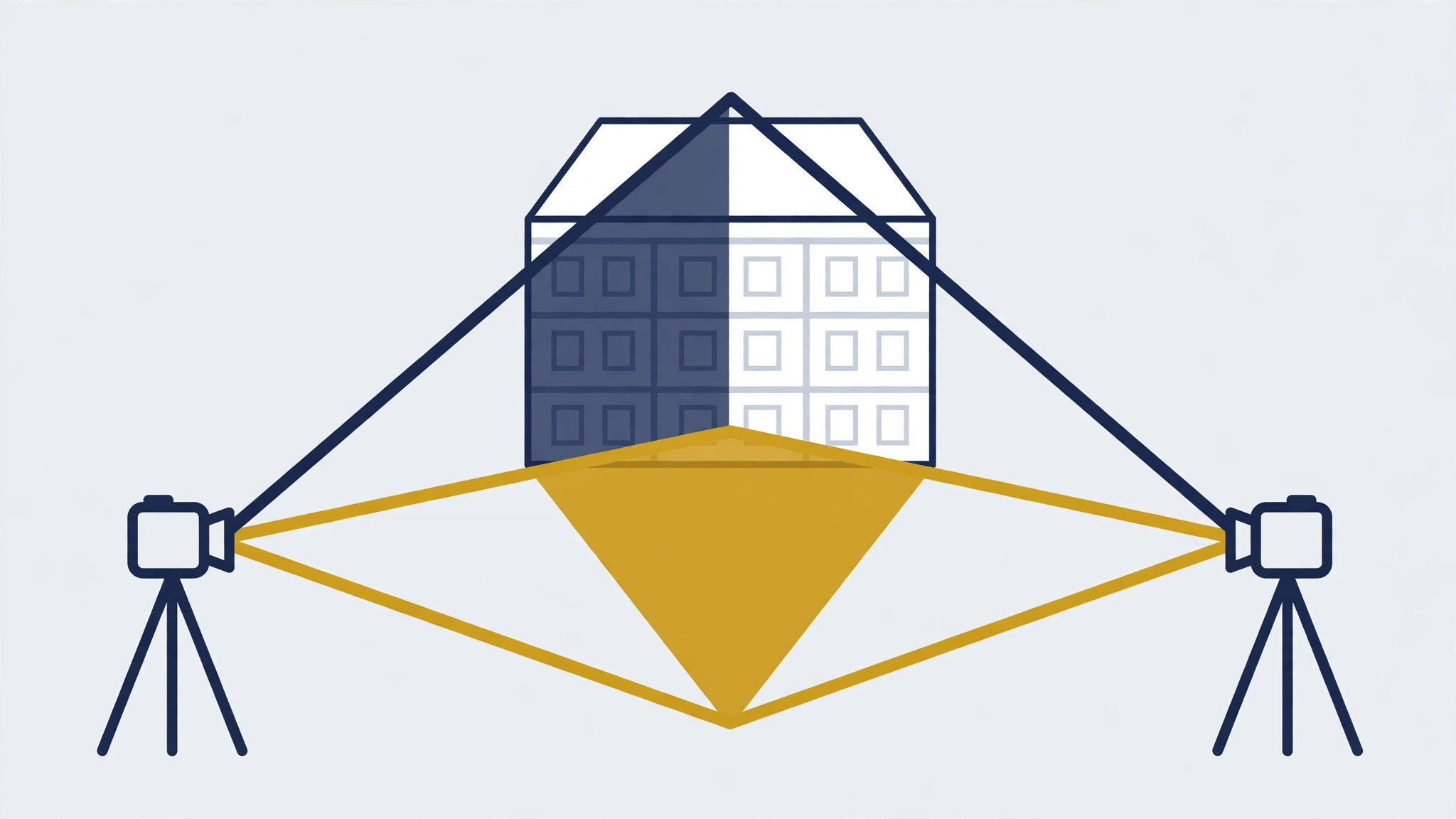
Structure from Motion (SfM) is the common modern method, and SfM software calculates camera positions and scene structure at the same time from the photo set. Bundle adjustment reduces errors across coordinates and camera positions through repeated adjustments until the matched points fit the camera model. Triangulation gives the core geometry: two or more camera positions view one point, and the intersection of the sight lines gives the point position. The triangulation in surveying and computer vision page explains the triangle geometry behind the calculation in plain terms.
Overlap controls success. Guidance for drone mapping commonly calls for 70 to 80 percent forward overlap and 60 to 70 percent side overlap (Source: TopoStreets, 2025). Forward overlap covers consecutive photos along one flight line, and side overlap covers neighbouring flight lines. Low overlap leaves gaps in matching, and high overlap adds processing time. For small objects, a full circle path with photos every 10 to 15 degrees gives strong coverage.
What Are the Main Types of Photogrammetry?
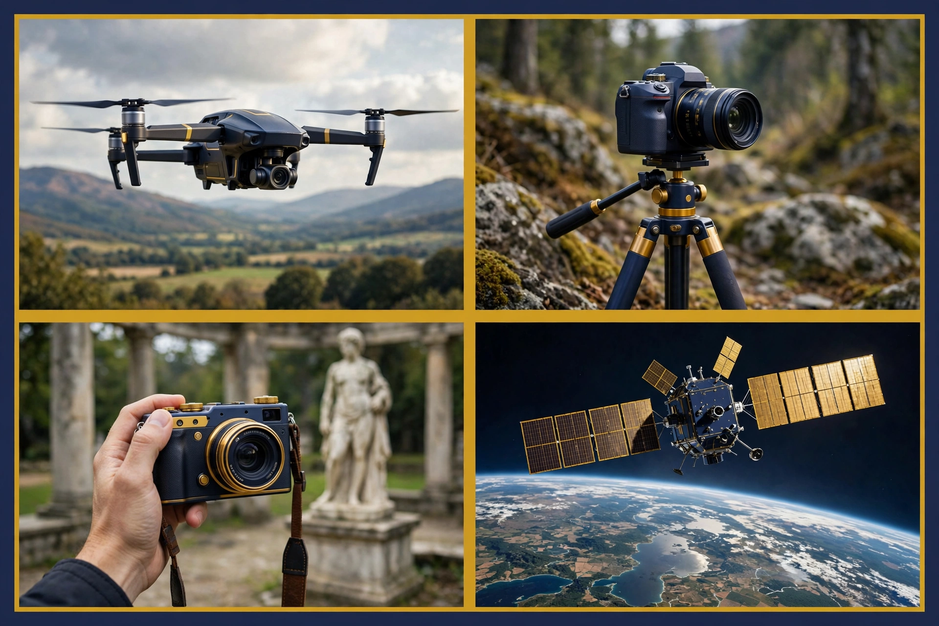
The main types of photogrammetry are aerial photogrammetry, terrestrial photogrammetry, and spaceborne photogrammetry, and close-range photogrammetry covers short-distance work within the terrestrial type. Photogrammetry types differ by camera position, scale, and coverage, and camera position decides the detail in the finished model.
Aerial Photogrammetry
Aerial photogrammetry uses photographs taken from aircraft or drones, and aerial photogrammetry maps large areas fast with a downward or angled camera. Drone photogrammetry uses drones that fly low, follow planned paths, and capture many overlapping photos in one session for sites, fields, roofs, and quarries. Aerial photogrammetry suits orthomosaics, elevation models, stockpile volumes, and progress records, and aerial photogrammetry gives less detail on vertical faces, so oblique drone photos or added ground photos help with walls and facades.
Terrestrial Photogrammetry
Terrestrial photogrammetry uses photographs taken from ground level, and terrestrial photogrammetry records fine detail on buildings, objects, and crime scenes. A handheld camera or a tripod camera captures the subject from planned ground positions for facades, interiors, statues, machinery, and evidence records.
Close-Range Photogrammetry
Close-range photogrammetry uses photographs taken at short distance, and close-range photogrammetry measures small objects and surfaces with high detail. Close-range work covers museum objects, fossils, machine parts, and building details, and a turntable, a fixed camera path, and a scale bar give strong results for small objects.
Spaceborne Photogrammetry
Spaceborne photogrammetry uses photographs or imagery from satellites, and spaceborne photogrammetry maps very large areas for base maps and change checks. Satellite imagery covers regions that aircraft cannot reach on a practical schedule, and satellite stereo pairs give elevation data at regional scale. Spaceborne results suit regional planning and disaster overviews rather than site-level measurement.
What Outputs Does Photogrammetry Produce?
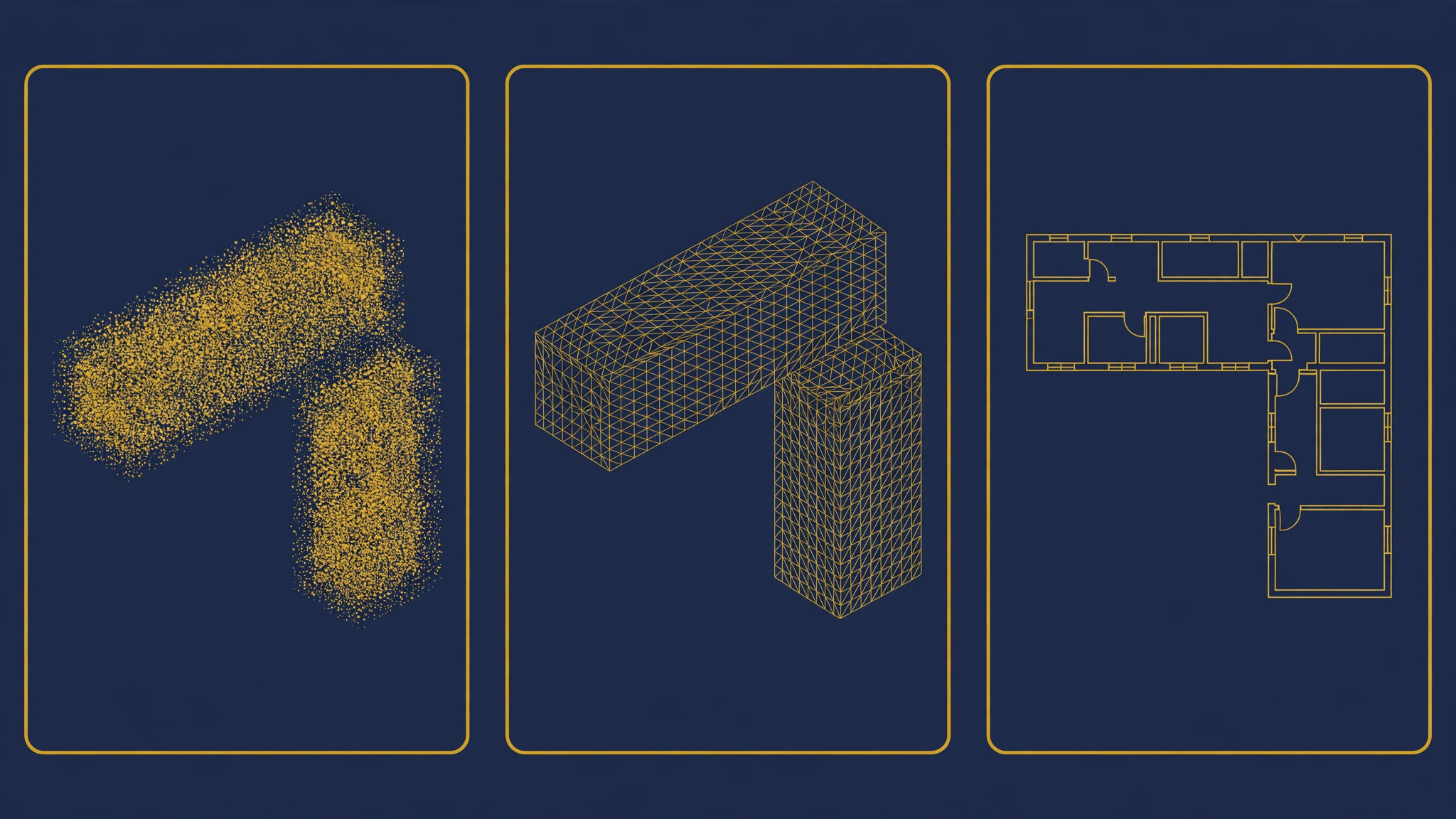
Photogrammetry produces point clouds, textured 3D meshes, orthomosaics, digital surface models, and digital elevation models, and each output serves a different check, map, or record need. Photogrammetry outputs share one photo set, and output choice depends on the question the reader needs to answer.
3D photogrammetry builds a full three-dimensional model from two-dimensional photos, and 3D photogrammetry extracts geometry and colour from the matched points. A point cloud is a large set of three-dimensional points that mark surfaces, and a point cloud supports measurement and export to mapping software. A mesh joins point cloud points into triangles to form a continuous surface, with texture from the original photos. An orthomosaic is a geometrically corrected map built from combined photos, and an orthomosaic keeps true scale for distance and area checks. A digital surface model records heights of ground, buildings, and vegetation, while a digital elevation model records bare ground heights.
| Output | What the output shows | Best use |
|---|---|---|
| Point cloud | Three-dimensional points on surfaces | Measurement, comparison, and export to mapping tools |
| Textured 3D mesh | Continuous surface with photo texture | Visual records, heritage models, and client review |
| Orthomosaic | Scale-correct stitched map image | Distance checks, area checks, and field maps |
| Digital surface model | Heights of ground and surface features | Roof checks, canopy checks, and volume checks |
| Digital elevation model | Bare ground heights | Flood checks, slope checks, and terrain planning |
Output quality checks matter at each stage. A sparse point cloud warns of weak overlap or poor light, a mesh with holes warns of missing angles or plain surfaces, and wavy lines on roads in an orthomosaic signal alignment errors.
What Is Photogrammetry Used For?
Photogrammetry is used for topographic mapping, architecture, engineering, construction, heritage recording, farming, filmmaking, forensics, and research, and photogrammetry gives each field measured visual records from photographs. Photogrammetry use grows where a visual record must also support measurement, comparison, or repeat checks over time.
Surveying and mapping form the oldest use. Photogrammetry supports topographic maps, land records, and orthomosaics for planning, and photogrammetry updates maps faster than ground-only survey work for large areas. Construction teams use photogrammetry for site records, progress checks, stockpile volumes, and as-built models, and weekly drone flights give dated records for payment and dispute checks. Architects and engineers use photogrammetry for facade records, damage checks, and roof surveys.
Heritage teams use photogrammetry to record fragile sites, monuments, and objects before restoration or loss, and a 3D record lets researchers measure a site after field access ends. Archaeologists use photogrammetry for excavation plans, since overhead photos record each layer before digging removes the layer. A drone survey of a glacier on Mount Stanley recorded a 29.5 percent surface area decline between 2020 and 2024 (Source: Project Pressure, 2024), and the survey shows how repeat photogrammetry supports change checks over years.
Farming teams use photogrammetry for crop checks, field maps, and drainage planning, and orthomosaics show growth patterns across whole fields in one view. Filmmakers and game studios use photogrammetry for sets, props, and characters with real surface detail. Forensic teams use photogrammetry for crash scenes and crime scenes, since a measured 3D record preserves positions after a scene clears.
Photogrammetry vs LiDAR: Which Method Fits the Job?
Photogrammetry fits jobs that need colour, texture, and low-cost capture in open light, while LiDAR fits jobs that need direct ranges through vegetation, in low light, or at high precision on plain surfaces. Photogrammetry and LiDAR often work best together, with photos giving colour and LiDAR giving ground heights under cover.
LiDAR (Light Detection and Ranging) sends laser pulses and times the return to measure distance, and LiDAR builds a point cloud from direct ranges rather than photo matching. LiDAR records ground points through gaps in vegetation, while photogrammetry records the top surface seen in photos. LiDAR works in low light, while photogrammetry needs light on the subject. Photogrammetry records full colour and texture by default, while LiDAR colour needs added camera data.
| Factor | Photogrammetry | LiDAR |
|---|---|---|
| Data source | Overlapping photographs | Laser pulses and return times |
| Colour and texture | Full colour from photos | Colour needs added camera data |
| Vegetation cover | Records top surface in photos | Records ground points through gaps in cover |
| Light needs | Needs light on the subject | Works in low light |
| Equipment cost | Lower entry cost with cameras and drones | Higher cost for scanners and sensors |
| Processing load | Heavy photo matching and texture work | Faster point cloud work in many cases |
| Best fit | Open sites, visual records, maps, heritage | Forests, bare earth models, precision surveys |
Choose photogrammetry for open construction sites, fields, roofs, heritage facades, and visual records where colour matters. Choose LiDAR for forest ground models, power line corridors, and surveys where vegetation hides the ground. Choose combined capture for complex sites, since photos define building edges clearly, and LiDAR defines ground heights where photos show only canopy tops. Voice of Wave readers who follow automated image and data workflows can read how automated software agents handle image and data workflows in AI Agent Development: A Business Guide for 2026.
How Accurate Is Photogrammetry?
Photogrammetry accuracy depends on overlap, camera calibration, ground control points, check points, and surface texture, and photogrammetry accuracy ranges from centimetre-level results on controlled surveys to metre-level errors on weak photo sets. Photogrammetry accuracy is a property of the full workflow, not a property of the camera alone.
Ground control points (GCPs) are marked points with known real-world coordinates, and GCPs anchor a model to scale and position. Check points are known points kept out of the adjustment, and check points give an honest error report for the finished model. A model that fits GCPs closely but misses check points holds a bias. Real-time kinematic (RTK) and post-processed kinematic (PPK) satellite positioning improve camera positions on drone flights and reduce the number of GCPs needed on open sites, and RTK and PPK do not remove the need for checks.
Ground sampling distance (GSD) is the ground size of one image pixel, and GSD sets the smallest detail the photo set can resolve. A lower flight height gives a smaller GSD and finer detail, while a higher flight gives a larger GSD and wider coverage. Camera calibration corrects lens distortion. Changing exposure between photos changes brightness matching, and moving shadows during a long flight change surface appearance between views.
Report accuracy with numbers from the actual project: GSD, the number and spread of GCPs, check point errors in metres or centimetres, and the output type. A report that gives only a camera model or a photo count does not prove accuracy.
What Software and Equipment Do Beginners Need?
Beginners need a camera, a planned photo path, control or scale references, and photogrammetry software that aligns photos, builds point clouds, and exports maps or models. A phone camera and free software can support a first small project, and larger jobs add drones, control points, and paid software.
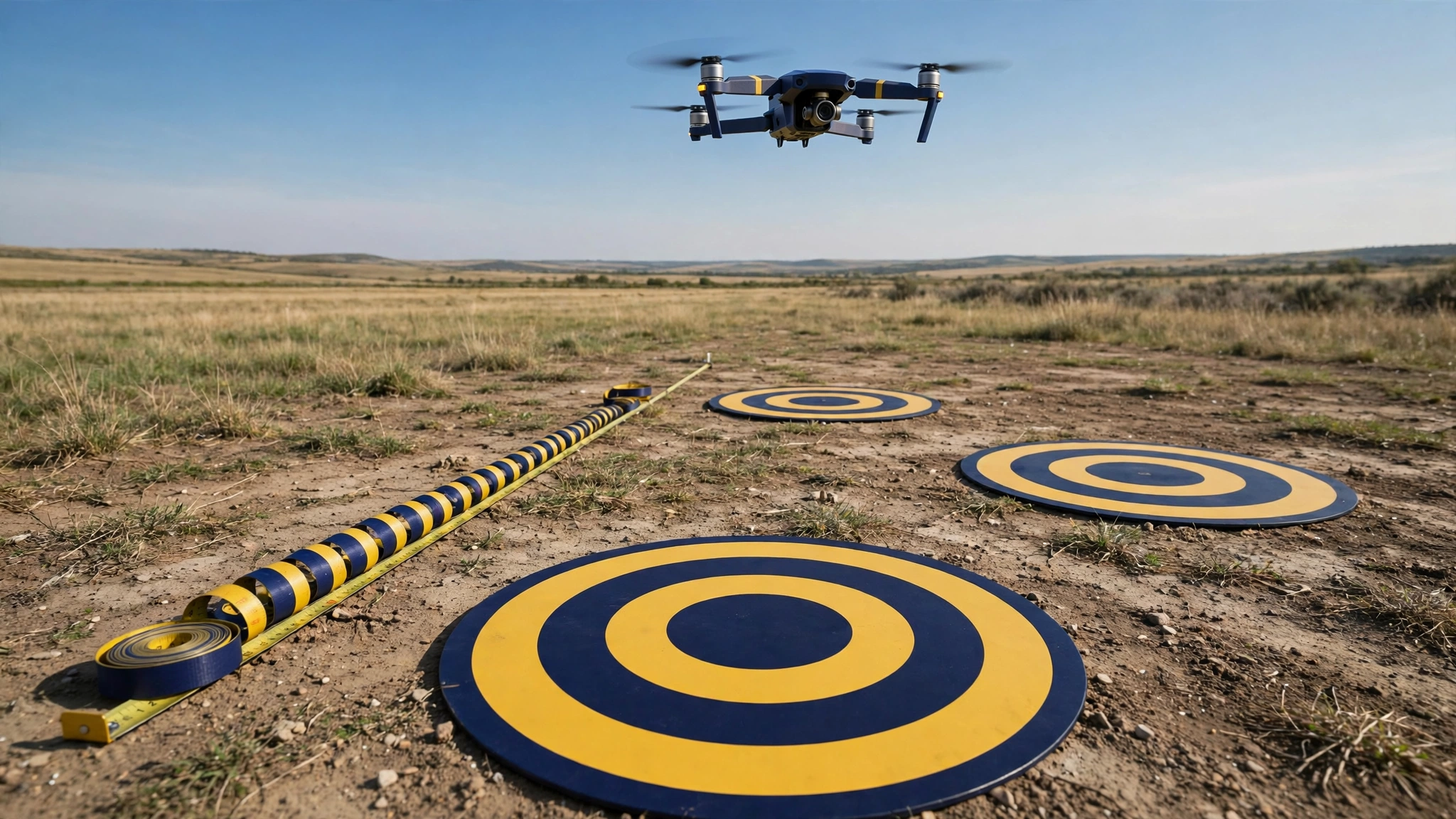
Camera options start with a phone camera for small objects and rooms, a handheld camera with manual settings for facades and objects, and a drone camera for roofs, fields, and sites. A tripod steadies ground photos, and a scale bar gives size for object models without GCPs. A measuring tape, printed targets, and a Global Navigation Satellite System (GNSS) receiver support control checks. A computer with a strong graphics card and ample memory speeds processing.
Software options include Agisoft Metashape for survey and heritage work, Pix4Dmapper for drone mapping and orthomosaics, RealityScan (formerly RealityCapture) for fast large datasets, 3DF Zephyr for small and mid-size projects, Meshroom for open-source work, and OpenDroneMap for open-source drone mapping. Metashape supports GCPs and dense outputs, Pix4Dmapper supports orthomosaics and elevation models, and Meshroom and OpenDroneMap lower the cost barrier for learning.
Overlap, stable light, and checked control points decide photogrammetry accuracy more than camera price does.
How Can You Start a First Photogrammetry Project?
A first photogrammetry project starts with a small, still, textured subject, a planned photo path with strong overlap, fixed camera settings, and a scale reference, and a first project ends with a checked model rather than a perfect model. A first project teaches the workflow, and later projects add scale, control points, and drone flights.
Pick a subject with texture and clear edges, such as a garden statue, a brick wall section, or a parked machine part. Avoid moving subjects, shiny metal, clear glass, and plain white walls for a first test, since those surfaces give software few points to match. A practical observation from a small handheld test: a smooth, plain base on a garden statue left gaps in the first mesh, while added low-angle photos gave the software points to match across the base.
Follow 8 steps for the first project:
- Choose a small, still, textured subject in steady light.
- Set fixed exposure, fixed focus, and the lowest practical ISO.
- Walk a full circle, taking a photo every 10 to 15 degrees.
- Add higher and lower angle photos for tops and undercuts.
- Place a scale bar or a measured tape beside the subject.
- Import photos, remove blurred photos, and align the photo set.
- Build a point cloud, mesh, and texture at medium settings.
- Measure a known length on the model and record the error.
Check the first model against a known length, and record the difference in centimetres. A small error supports trust in other measurements from the same model, while a large error points to weak overlap, poor focus, or missing angles. Repeat the same subject with a different photo path, and keep notes on light, overlap, photo count, and settings. Voice of Wave publishes technology guides for general readers, and photogrammetry fits that coverage as a practical method readers can test with a phone camera.
What Are the Limits and Common Errors?
Photogrammetry limits include shiny, clear, plain, moving, and vegetation-covered surfaces, and common errors include weak overlap, changing light, blurred photos, and missing control checks. Photogrammetry limits come from photo matching, since software needs visible, stable points in at least two views.
Shiny and clear surfaces reflect light differently from each angle, so matched points shift or vanish between photos. A matte spray or a dusting of powder helps on small objects, while added angled photos help on larger shiny faces. Plain surfaces give few points, so added targets, tape marks, or textured backgrounds give software stable features. Moving subjects break matching. Vegetation moves in wind and hides ground, so calm conditions and added LiDAR data help where ground heights matter.
Common errors start before processing. Low overlap leaves holes, and a single circle path leaves tops and bases thin. Changing exposure, white balance shifts, and moving shadows change pixel values between views. Blurred photos add false points. Missing control points leave scale and position unchecked.
Fix errors in order: check sharpness, overlap, and light stability, add angles, add targets, and add control points. Reprocess at medium settings before high settings. Keep the photo set, settings, and error report with each output.
Conclusion
Photogrammetry is the science and technology of obtaining reliable information about physical objects and the environment from photographs, and photogrammetry turns overlapping photographs into measurements, maps, and 3D models for mapping, construction, heritage, and research. Photogrammetry works through planned photos, point matching, triangulation, and checked outputs, and types differ by camera position from ground, air, close range, and space. Outputs include point clouds, meshes, orthomosaics, and elevation models, and accuracy follows overlap, calibration, control points, and surface texture. LiDAR suits vegetation and low light work, while photogrammetry suits colour, texture, and low-cost open site work. A first project with a small textured subject, fixed settings, strong overlap, and a scale check teaches the full method. Voice of Wave covers practical technology methods of this kind, and readers can start with one subject, one photo path, and one checked model.
Browse the latest articles on the blog: Browse the blog
Frequently Asked Questions
What is photogrammetry in simple terms?
Photogrammetry is the measurement of real objects and places from photographs. Software matches the same points across overlapping photos taken from different angles, calculates camera positions, and builds measurements, maps, or 3D models from the matched points, without touching the subject.
How does photogrammetry work?
Photogrammetry works through planned overlapping photos, point matching, and triangulation. Software finds shared points in many views, works out where each camera stood, and calculates three-dimensional positions from intersecting sight lines, then builds a point cloud, mesh, or map for the subject.
What is photogrammetry used for?
Photogrammetry is used for mapping, construction records, heritage recording, farming checks, film and game assets, forensic scene records, and research. Each use needs a measured visual record, such as an orthomosaic for a field, a mesh for a monument, or a model for a crash scene.
How accurate is photogrammetry?
Photogrammetry accuracy depends on overlap, calibration, ground control points, and surface texture. Controlled surveys with good overlap and checked control points reach centimetre-level results, while weak photo sets with poor light or low overlap can hold metre-level errors, so check points must confirm each project.
Photogrammetry vs LiDAR: which is better?
Neither method is better for every job, since the best choice follows the job. Photogrammetry gives colour, texture, and lower entry cost in open light, while LiDAR gives direct ranges through vegetation and in low light, and combined capture suits complex sites with both needs.
Can I do photogrammetry with a phone camera?
Yes, a phone camera can support photogrammetry for small objects and rooms. Use fixed exposure and focus, strong overlap, steady light, and a scale reference, then process the photos in photogrammetry software and check the model against a known length before trusting other measurements.